The photocells described in this page work with the Arduino-Visual Basic Interface (http://analisisdelaconducta.net/?page_id=2).
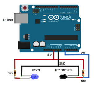
Follow the diagram to connect each photocell. Up to 6 photocells can be used with an Arduino Uno board and up to 16 with an Arduino Mega board.
After setting up the hardware, upload the following program to the Arduino board. This program will be used only during calibration.
To calibrate the photocell it is necessary to obtain the threshold value of the analog input to determine when a response will be recorder. Download and execute the following program to obtain the threshold value.
Please note that if the values read do not change when the light is blocked and unblocked, there must be a connection error.
The Arduino-Visual Basic Interface requires two programs, one for the Arduino board (firmware) and another, written in Visual Basic, to generate the schedule of reinforcement and record responses.
The threshold value obtained with the calibration program must be entered in the Arduino program before uploading it to the Arduino board.
Additionally, there are two versions of the programs: for recording one or two responses.
Download the file containing the Arduino program
For one response
For two responses
Arduino_Program_Photocell_Concurrent.ino
Download the folder containing the Visual Basic programs for generating schedules of reinforcement.
For schedules with one response
For concurrent schedules with two responses
Visual_Basic_Program_Concurrent.zip